How to Select a Lithium-Ion Battery Charge Management IC

Get valuable resources straight to your inbox - sent out once per month
We value your privacy
John B. Goodenough, considered the father of lithium-ion (Li-ion) batteries, became the oldest Nobel Prize winner when he was awarded the Nobel Prize in Chemistry in 2019 for his pioneering work. Nowadays, Li-ion batteries are utilized in all aspects of life for most consumers since they make electronic devices lightweight and long-lasting. For example, most mobile phones rely on a Li-ion battery for longer runtimes, portability, and convenient charging.
有效电荷锂batte是很重要的ries for maximum use.
How to Charge Lithium-Ion Batteries
First, let’s analyze the Li-ion battery charging process. The charging process can be divided into four different stages: trickle charge, pre-charge, constant-current charge, and constant-voltage charge.Figure 1shows the charging curve of a typical lithium-ion battery.
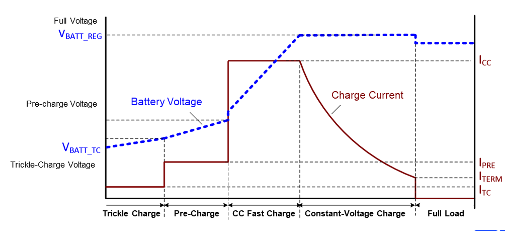
Figure 1: Lithium-Ion Battery Charging Curve
It seems simple, but there are many parameters to consider when choosing a battery charging solution.Figure 2shows the four main considerations when selecting a solution.
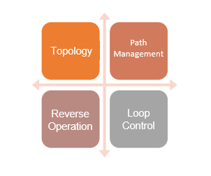
Figure 2: Battery Charger Design – Key Considerations
These considerations are described in further detail below:
Topology
Battery charger system designers must choose the topology based on input voltage range, battery configurations, charging currents, and other system-level priorities(see Figure 3).
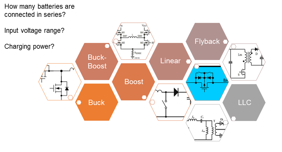
Figure 3: Battery Charger Topologies
For example, most portable devices charge from a USB port. There are two main USB types:
- USB Type-A: Usually 5V at a 1.5A maximum, this USB type can support fast charging (among other standards) up to 12V
- USB Type-C: 5V at 3A maximum. If USB-PD is supported, this can be increased to 20V at 5A
If the device is charging via the USB port, it must always support 5V operation. For example, for batteries in series (maximum VBATT ≥ 8.4V), use boost or buck-boost topology. If the device is not charging from a USB port, it is recommended to use buck topology because the input voltage always exceeds the battery voltage.
Control Loops
A major challenge for battery management ICs is that they have multiple control loops. Not only do they need to manage the input voltage and current, they must also manage the system’s power, battery charging current and voltage, battery temperature, and other parameters(see Figure 4). For example, the system often has to adjust battery charging current according to the battery temperature.
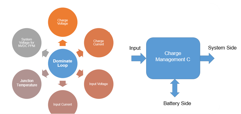
Figure 4: Various Control Loops in Battery Charger IC
Power Path Management
The power path management control loop adjusts the battery charge current dynamically, based on the input source current capability and the system load current requirements. This ensures that the system receives the required current while using excess charge to charge the battery.
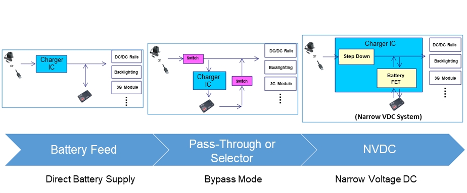
Figure 5: Battery Charger System Architectures
Depending on the battery charger features, there are three typical architectures.
The first architecture connects the battery directly to the system supply, and requires the battery voltage to reach the minimum system voltage to operate.
The second is the pass-through approach, which uses external switches to manage the battery charging and system paths.
The third architecture is NVDC power path management, which is a common approach that has the following advantages over the previous two architectures:
- The system can start instantly, even with a low battery voltage
- The system voltage closely follows the battery voltage to reduce the voltage stress of the system components
- When the input power is limited, the battery can supplement the system
- The system can be disconnected from the battery to support transport mode
Figure 6shows NVDC charger charging curve operation.
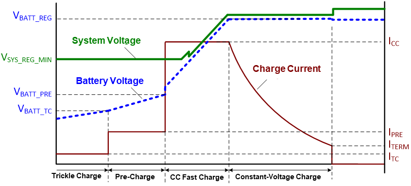
Figure 6: Li-Ion Charging Curve with NVDC Features
When the battery voltage is relatively low, the system voltage is regulated at the lowest operating point (VSYS_REG_MIN in Figure 6). When the battery voltage approaches VSYS_REG_MIN, the battery and system voltages closely track each other. Therefore, regardless of the state of the battery, the system voltage is always maintained in a narrow range. Figure 7 shows real-world scope plots.
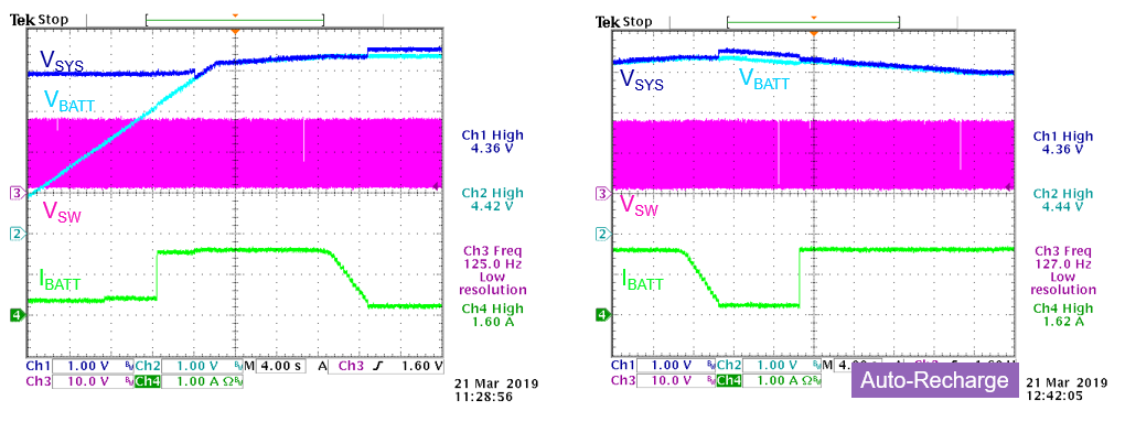
Figure 7: Typical Charging Curve (Working Conditions: VIN= 16V, VBATTRamping from 0V, ICHG = 1.84A, ISYS= 1A)
Reverse Operation
The battery charger operations discussed above have used the input source to charge the battery or power the system. It is also possible to provide operation in the reverse direction, such as USB On-the-Go (OTG) function. A battery charger with USB OTG functionality allows the device’s internal battery to power devices back through the device input port.
MP2731 Battery Charging IC
If your application requires NVDC power path management and OTG function, theMP2731battery charger IC can perfectly meet your needs(见图8).
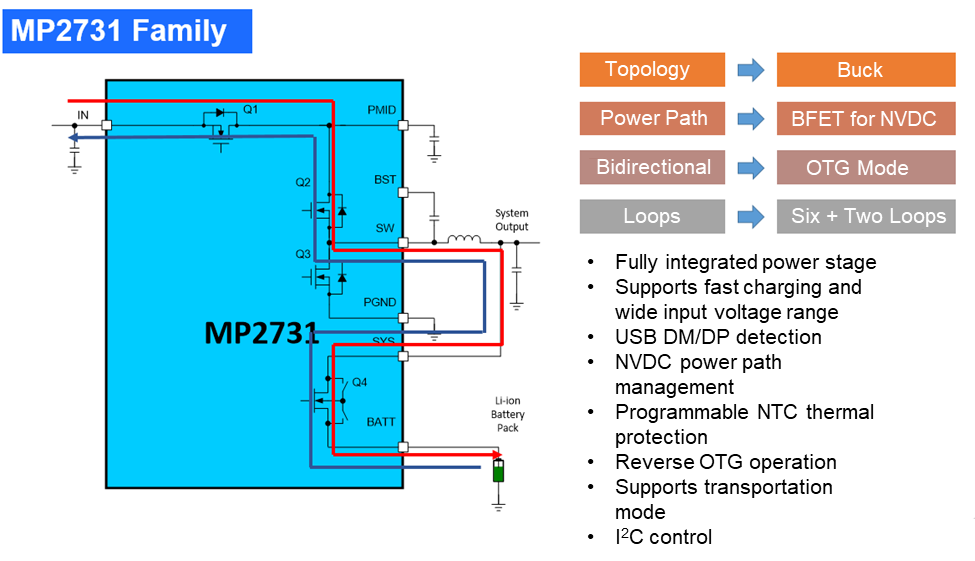
Figure 8: MP2731 Schematic and Main Features
TheMP2731is a fully integrated battery charger that supports these modes and provides high efficiency, as well as impressive thermal performance.
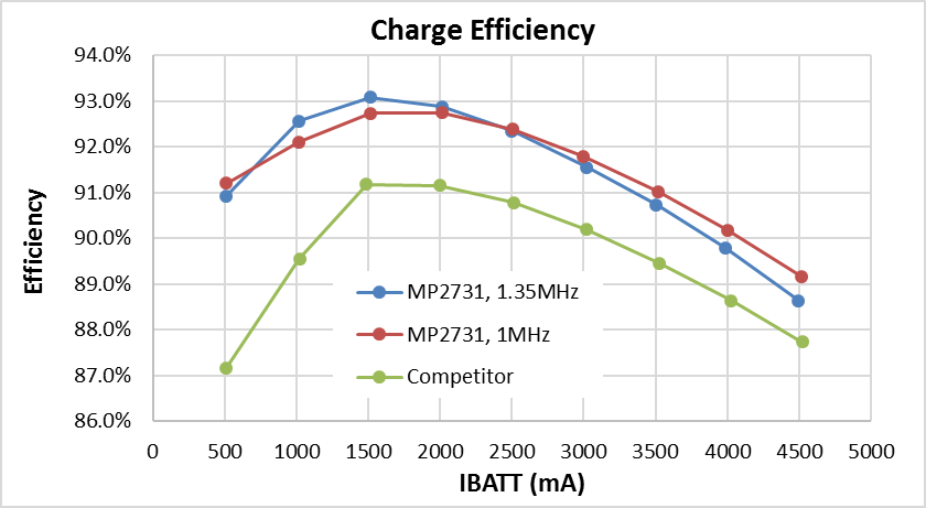
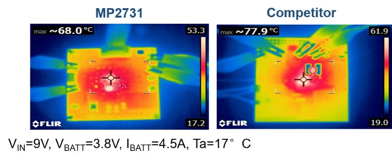
Figure 9: High Efficiency and Thermal Performance
As Li-ion batteries continue to be used in modern appliances and systems, it is vital to continuously evaluate how to make them more efficient and cost-effective. With so many architectures and chargers to choose from, MPS can streamline the process with products like theMP2731.
_________________________
Did you find this interesting?Get valuable resources straight to your inbox - sent out once per month!
Technical Forum
 Latest activity a year ago
 11 Comments
Latest activity 6 months ago
3 Comments
Latest activity 2 years ago
8 Comments
11 Comments
Latest activity 6 months ago
3 Comments
Latest activity 2 years ago
8 Comments
Log in to your account
Create New Account